

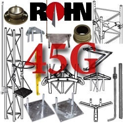
45G Base & Top Plates, Roof
Mounts, Tools, Brackets,
Bearings, Shelves, Hardware
45G Tower Wall Mounts and
Brackets, Tower Side and Top
Antenna Mast Pipe Mounts
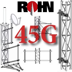
45G Imbedded Bases, Tower
Middle, Straight, Tapered,
Insulator, Top Cap Sections
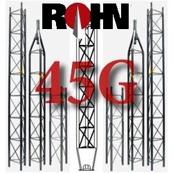
45G Self-Supporting Towers
Pre-Engineered Kits with 10,
20, 30, 35, 40, 45 foot height
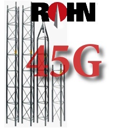
45G Bracketed Tower Kits are
(2) Brackets to Building Side
Wall to rise above Roofline
45G Guyed Tower Kits from
40 to 300 foot with 70, 90,
110, 130 MPH Wind Load
The ROHN 45G Multipurpose Tower
Tower & Foundation Installation
Tower and foundation installations should be performed by qualified and experienced personnel using construction drawings. This document is to serve as a guide for sizing and buying the 25G tower. All types of antenna installations should be thoroughly inspected by qualified personnel and re-marked with appropriate danger and anti-climb labels at least twice a year to ensure safety and proper performance.
Wind Loading
Wind Loading, Antenna Loading and Wind Survivability ratings vs. Height Documentation Provided by ROHN is available here as a Resource, but is by no means complete by itself or a substitution; for Engineering Conducted Specific to your Application. Contact Us with any Questions you may have regarding Use prior to Purchase. All Information regarding the ROHN 25G Tower line, Parts and Accessories is as accurate and complete as we can possibly provide given that this Resource Offering is subject to change without Notice and is beyond Our Control.
DESIGN NOTES:
1. Tower designs are in accordance with ANSI/TIA-222-F-1996 and ANSI/TIA-222-G-2005, Class I Structures.
2. Design assumes towers are installed on level ground. Lower EPA values will apply for roof mounted towers or for sites located on unusual terrain.
3. Designs assume one 1/2" and one 7/8" diameter lines on each tower face.
4. Anchor radius is from tower base to intersection of anchor rod with ground.
5. Tower designs and guy chord lengths shown are based on level ground. Initial tensions for guys in pounds at 60º Fahrenheit are shown in ( ).
6. Antenna and mounts are assumed symmetrically placed at the tower top.
PARTS LIST NOTES:
1. Items listed are required for complete (ground) guyed towers. Base and anchor details will be required for installation on roofs or for sites located on unusual terrains and wind loading criteria, for all roof type installations.
2. Standard guys provided with each standard tower include an additional 6% length.
3. Anchor grounding (AGK1GGX) and base grounding (BGK3GGX) are included with the tower material.
4. Installation information and a safety package (P/N: ACWS) are included with each tower
45G Buyers Guide
![]()
Guides and specification sheets are found on every products specifications tab. For a complete list of these guides organized alphabetically by manufacturer part number/code, visit the detailed information and Specifications page. These documents should answer most of the questions you may have on the ROHN 45G product line
Bringing reception to fringe areas outside the Suburban Broadcast Area. Plus everything is made right here in America. ROHN fabricates their towers from the highest quality steel. While maintaining mill certification on the raw materials they receive so they can verify the material composition of each structural member. With a focus on quality, their fabrication facility has been awarded Certification by the American Institute of Steel Construction and the Canadian Welding Bureau. Plus the City of Los Angeles, CA and Clark County, NV they are a certified fabricator. The ROHN facility and it's staff can produce a superior grade tower and supporting hardware that will meet your standards and weather the test of time.
ROHN Towers, Accessories and their Construction/Assembly Assistance are also available.
Just contact us at 877-660-0974 at anytime for assistance.
GUIDELINES FOR THE PREPARATION OF A GEOTECHNICAL REPORT
I. PURPOSE AND INTENT
a) The intended purpose of these guidelines is to assist the customer and/or owner to retain the services of a Geotechnical Engineer.
b) It is not ROHN´s purpose or intent to supersede the Geotechnical Engineer´s knowledge, judgement and/or experience. It is the Geotechnical Engineer´s responsibility to add or delete from these items, based on local site conditions and other factors.
c) Additional information is provided in ANSI/TIA-222-G Annex G "Geotechnical Investigations".
II. DISCLAIMER
a) ROHN will not accept any liability, either expressed or implied, for the use of, and omissions in, these guidelines.
III. EXPLORATORY BORINGS
a) Borings should be taken at tower legs for self-supporting towers and at the base and anchor points for guyed towers. For small self-supporting towers, two borings may suffice. For large self-supporting towers, one boring should be taken at each tower leg. A "small" self-supporting tower is assumed to have a face width less than 20 feet and a compression load less than 50 kips per leg. For pole structures, one boring may suffice.
b) The minimum boring depth should be 30 feet for pole structures, self-supporting towers and guyed tower bases. For guyed tower anchors, the minimum depth should be 15 feet. The actual depth of boring must be determined by the Geotechnical Engineer based on reactions, soil conditions and the type of foundation recommended.
c) If borings cannot be advanced to the desired depth, rock corings should be taken. Rock Quality Designation (RQD) values and compressive strengths should be determined.
IV. GEOTECHNICAL REPORT
a) The following properties, for each soil layer encountered, should be determined by field or laboratory testing and summarized in the geotechnical report:
1. Soil classification and elevations
2. Standard penetration values
3. Unconfined compression strength
4. Angle of internal friction
5. Cohesion
6. "In-Situ" soil density and moisture content
7. Rock quality designation (RQD) and percent rock sample recovered
8. Other properties unique to site conditions
b) The following items should be discussed in the geotechnical report:
1. Geological description of site
2. Observed and expected ground water conditions
3. Expected frost penetration depth
4. Corrosion potential of soil and corrosion protection recommendations
5. Site access and potential construction difficulties
6. Dewatering or site drainage requirements
7. Backfill material recommendations
8. Settlement considerations
9. Additional information to aid foundation designer
10. Recommended types of foundations
11. Design parameters for uplift, download and lateral load
12. Factor of safety considered when allowable vs. ultimate design parameters are provided
13. Recommended construction techniques and inspections


-
ROHN TOWERS & MASTS Sections, Mounts & Parts
- ROHN TELESCOPIC MAST Guy Wire Brackets Mounts
- ROHN WALL BRACKETS HD MAST & PIPE MOUNTS
- ROHN ROOF ANTENNA MAST TRIPOD MOUNTS
- ROHN NON-PENETRATING Roof Mount Antenna Mast
- ROHN 25G Towers & Parts
- ROHN 45G Towers & Parts
- ROHN 45GSR Tower | Parts
- ROHN 55FK Tower Series
- ROHN 55G Towers & Parts
- ROHN 65G Towers & Parts
- ROHN RSL Towers & Parts
- ROHN RTL Towers & Parts
- ROHN 80/90 Tower Series
- ROHN Tower & Site Accs.
- ROHN Monopole Towers
- ROHN Tower Grounding
- ROHN Tower Guy & HDWR
- ROHN Tools & Safety Gear
- Tower Paint & Galvanize
- ROHN Catalog Download
- Tower Lighting & Marking
- HDG Steel Mounting Pipe
- ALUMINUM TOWER KITS Sections, Mounts & Parts
- TOWER SAFETY SYSTEMS Climbing, Lighting & Paint
- STEEL STRUT CHANNEL SLOTTED & GALVANIZED
- EHS STRAND & GUY WIRE Grips, Turnbuckle, Anchor
- ROHN TOWER MOUNT ANTENNA ASSEMBLIES
- HD WALL MOUNT ANTENNA ASSEMBLIES
- NON-PENETRATING ROOF ANTENNA MAST MOUNTS
- HDG, GALVANIZED PIPE and ALUMINUM TUBING
- PIPE to PIPE PARALLEL POLE MOUNT CLAMP SETS
- PIPE to PIPE CROSSOVER PERPENDICULAR CLAMPS
- HDG C & V-CLAMP Halves Alligator JAW Pipe Mount
- ANTENNA MAST POLES and TELESCOPIC MASTS
- ANTENNA MAST MOUNTS for WALL, ROOF, CHIMNEY
- ANTENNA ROOF MOUNTS PEAK PITCH EAVE GABLE
- GROUNDING & BONDING Wire Blocks Clamps Rods
- HD THIMBLES SHACKLES CLAMPS for Strand & Guy
- BOLTS NUTS WASHERS and TOWER JOINT KITS
- EYE Bolts J Bolts Clamps Pier Pins Threaded Rods
- SQUARE/ ROUND U-BOLTS HDG & PRE-GALVANIZED
- Broadband OSP Cable Equipment Hardware
- Wholesale and Excess Inventory Closeouts


