

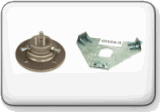
Original OEM Plates, Brackets,
Bearings, Shelves, Hardware
Mounts and other Accessories
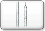
Middle, Top Cap, Solid Rail, Base
and Specialty Tower Sections to
Build a ROHN Tower Installation
Original OEM Brackets,
Mounts and Tower
Accessories

ROHN G Series are available as
self-supporting tower in Kits that
are Specifically Pre-Engineered

ROHN 65G Camera Tower Kits
TIA/EIA-222-G Wind to 110 MPH
Structure Class II / Exposure C
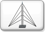
Pre-Engineered ROHN Tower
Kits Wind Speeds from
70 to 130 MPH

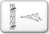
The 65G Series Rohn Tower
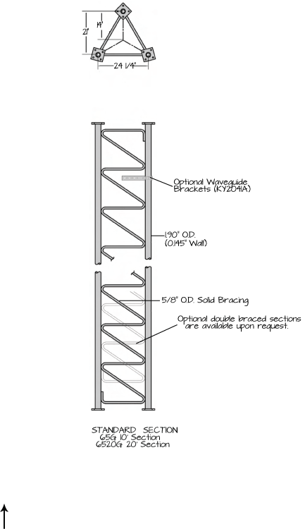
The 65G is designed to provide excellent rigidity and strength in applications up to 500´. This high strength design covers a wide variety of communication uses. The 65G is completely prefabricate in welded sections, allowing for quick and convenient installation.
Tower and foundation installations should be performed by qualified and experienced personnel using construction drawings. This document is to serve as a guide for sizing and buying the 65G tower. All types of antenna installations should be thoroughly inspected by qualified personnel and re-marked with appropriate danger and anti-climb labels at least twice a year to ensure safety and proper performance.
Wind Loading, Antenna Loading and Wind Survivability ratings vs. Height Documentation Provided by ROHN is available here as a Resource, but is by no means complete by itself or a substitution for Engineering Conducted Specific to your Application. Contact Us with any Questions you may have regarding Use prior to Purchase. All Information regarding the ROHN 65G Tower line, Parts and Accessories is as accurate and complete as we can possibly provide given that this Resource Offering is subject to change without Notice and is beyond Our Control.
DESIGN NOTES:
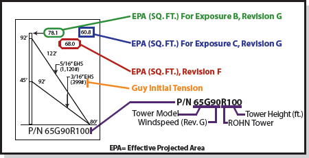
1. Tower designs are in accordance with ANSI/TIA-222-F-1996 and ANSI/TIA-222-G-2005, Class I Structures, Topographical Category 1.
2. Design assumes towers are installed on level ground. Lower EPA values will apply for roof mounted towers or for sites located on unusual terrain.
3. Designs assume two 7/8" diameter lines on each tower face.
4. Anchor radius is from tower base to intersection of anchor rod with ground.
5. Tower designs and guy chord lengths shown are based on level ground. Initial tensions for guys in pounds at 60º Fahrenheit are shown in ( ).
6. Antenna and mounts are assumed symmetrically placed at the tower top.
PARTS LIST NOTES:
1. Items listed are required for complete (ground) guyed towers.
2. Base and anchor foundations listed refer to standard foundation designations.
3. Guys provided with each standard tower are based on level ground conditions with an additional 6% length.
4. Rev G anchor grounding (AGK1GGX) and base grounding (BGK3GGX) are included with the tower material.
5. Assembly Drawings and a safety package (P/N: ACWS) are included with each tower.
6. Parts lists are subject to change based on availability or revised design criteria.
![]()
This Buyers Guide will answer many questions you may have on this Product Line.
ROHN Tower series is the Workhorse of America's Large and Small Communications needs; from Governments, Institutions, Space Program, Olympics, TV AM FM Broadcast, Terrestrial Microwave to Business-Band Radio, HAM Radio Operators, to Off-Air Antenna TV and DTV Reception in Fringe areas outside the Surburban Broadcast Area. ROHN fabricates their towers from the highest quality steel. They maintain mill certification on the raw materials they receive to verify the material composition of each structural member. With a focus on quality, their fabrication facility has been awarded Certification by the American Institute of Steel Construction and the Canadian Welding Bureau. They have also been approved by the City of Los Angeles, CA and Clark County, NV as a certified fabricator. They are confident that their facility and staff can produce superior grade towers and poles that will meet your standards and weather the test of time. ROHN Towers, Accessories and their Construction/Assembly Assistance are also available via 3StarInc.com... Call 877-660-0974 at anytime for assistance.
GUIDELINES FOR THE PREPARATION OF A GEOTECHNICAL REPORT
I. PURPOSE AND INTENT
a) The intended purpose of these guidelines is to assist the customer and/or owner to retain the services of a Geotechnical Engineer.
b) It is not ROHN´s purpose or intent to supercede the Geotechnical Engineer´s knowledge, judgement and/or experience. It is the Geotechnical Engineer´s responsibility to add or delete from these items, based on local site conditions and other factors.
c) Additional information is provided in ANSI/TIA-222-G Annex G "Geotechnical Investigations".
II. DISCLAIMER
a) ROHN will not accept any liability, either expressed or implied, for the use of, and omissions in, these guidelines.
III. EXPLORATORY BORINGS
a) Borings should be taken at tower legs for self-supporting towers and at the base and anchor points for guyed towers. For small self-supporting towers, two borings may suffice. For large self-supporting towers, one boring should be taken at each tower leg. A "small" self-supporting tower is assumed to have a face width less than 20 feet and a compression load less than 50 kips per leg. For pole structures, one boring may suffice.
b) The minimum boring depth should be 30 feet for pole structures, self-supporting towers and guyed tower bases. For guyed tower anchors, the minimum depth should be 15 feet. The actual depth of boring must be determined by the Geotechnical Engineer based on reactions, soil conditions and the type of foundation recommended.
c) If borings cannot be advanced to the desired depth, rock corings should be taken. Rock Quality Designation (RQD) values and compressive strengths should be determined.
IV. GEOTECHNICAL REPORT
a) The following properties, for each soil layer encountered, should be determined by field or laboratory testing and summarized in the geotechnical report:
1. Soil classification and elevations
2. Standard penetration values
3. Unconfined compression strength
4. Angle of internal friction
5. Cohesion
6. "In-Situ" soil density and moisture content
7. Rock quality designation (RQD) and percent rock sample recovered
8. Other properties unique to site conditions
b) The following items should be discussed in the geotechnical report:
1. Geological description of site
2. Observed and expected ground water conditions
3. Expected frost penetration depth
4. Corrosion potential of soil and corrosion protection recommendations
5. Site access and potential construction difficulties
6. Dewatering or site drainage requirements
7. Backfill material recommendations
8. Settlement considerations
9. Additional information to aid foundation designer
10. Recommended types of foundations
11. Design parameters for uplift, download and lateral load
12. Factor of safety considered when allowable vs. ultimate design parameters are provided
13. Recommended construction techniques and inspections


