


ROHN 45G Complete 130 Foot 130/ 110 MPH Guyed Tower 45G130R130
ROHN 45G Complete 130 Foot 130 MPH (REV. G) 110 MPH (REV. F) Guyed Tower
This Product Order Supplies the Following BOM (Less Foundation and Installation) in accordance for Use as a 130 Foot ROHN 45G Tower with EPA's (Effective Projected Area) Ratings for 130 MPH (REV. G) or 110 MPH (REV. F). Refer to Larger Image for EPA Information.
| 45G130R130 | ||
|---|---|---|
| QUANTITY | PART NUMBER | DESCRIPTION |
| 1 | APL45G | Top Beacon Plate for 45G |
| 1 | 45GL5* | 10' Tower "Lug" Section for 5/16" Guy Wire |
| 12 | 45G | 10' Tower Section |
| 12 | 45JBK | Bolt Kit for 45G Tower Section |
| 1 | BPC45G | Standard Concrete Base Plate |
| 3 | GA45GD | Guy Wire Bracket |
| 525 FT | 5/16" Guy Wire (aka ROHN 142265) | |
| 425 FT | 1/4" Guy Wire | |
| 350 FT | 3/16" Guy Wire | |
| 9 | PLP-115 | Yellow Plastic Guard for Guy Wire |
| 6 | BG2146 | 5/16" Big Grip Pre-Formed Deadends |
| 6 | BG2144 | 1/4" Big Grip Pre-Formed Deadends |
| 6 | BG2142 | 3/16" Big Grip Pre-Formed Deadends |
| 6 | 7/16THH | 7/16" Thimble |
| 6 | 3/8THH | 3/8" Thimble |
| 6 | 5/16THH | 5/16" Thimble |
| 9 | 5/8TBE&J | 5/8" x 12" Turnbuckle - Eye-to-Jaw |
| 3 | TBSAFETY | Turnbuckle Safety Wire and Clamps Kit |
| 3 | GAC5655TOP | Anchor Rod with 5 Hole Equalizer Plate |
| 1 | AGK1GGX |
Anchor Rod Ground Kit This Kit Includes: (3) 15' of 7/16 EIP IWRC RRL (3) 5/8" x 10' Galvanized Ground Rod (aka 6260) (3) 3/4" Clamp No. 8034 WB (aka 340016) (3) CPC.5/.75 - Anchor Rod Clamp |
| 3 | BGK3GGX |
Tower Base Section Grounding Kit This Kit Includes: (1) 15' of 7/16 EIP IWRC RRL (1) 5/8" x 10' Copper Clad Ground Rod (1) 3/4" Clamp Ground Rod Clamp (1) CPC1/1.25 - Anchor Rod Clamp |
| 3 | CPC1/1.25 | Anchor Rod Clamp |
| 1 | 3/4x12PP | Pier Pin Insert for 45G Tapered Base |
| 1 | ASSEMBLY GUIDE | |
This 45G Tower is to be used in a Guyed Configuration according to Specifications in the ROHN Catalog. As a Guyed Structure, a 130 MPH rated Tower can rise to a maximum of 150 feet. Consult ROHN Catalog Links at Footer Section at Bottom of Page for more ROHN 45G Tower Details.
This Item Ships LTL Freight ONLY...

ROHN 25G Self-Supporting Tower
The Self-Supporting G-Series Towers offer an easy, low-cost solution to get light weight antennas in the air quickly. By using the G-Series tower as a self-supporting structure, you minimize land area usage. They are functional in a wide variety of wind speeds, with and without ice. See ROHN´s standard design to help identify the right structure for your project. Theses are the same sturdy, robust tower sections that ROHN has fabricated for years. Each larger model allows for more loading capacity.
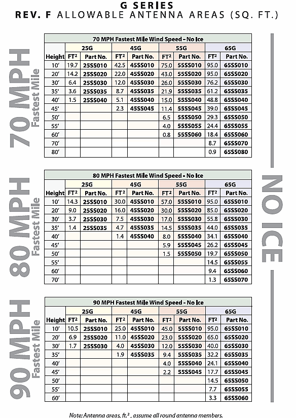
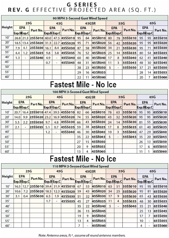
Wind Loading, Antenna Loading and Wind Survivability ratings vs. Height Documentation Provided by ROHN is available here as a Resource, but is by no means complete by itself or a substitution for Engineering Conducted Specific to your Application. Contact Us with any Questions you may have regarding Use prior to Purchase. All Information regarding the ROHN 25G Tower line, Parts and Accessories is as accurate and complete as we can possibly provide given that this Resource Offering is subject to change without Notice and is beyond Our Control.
DESIGN NOTES:
1. Tower designs are in accordance with approved national standard ANSI/EIA-222-F.
2. All towers must have "fixed" bases. Pinned bases may not be used.
3. Designs assume transmission lines symmetrically placed as follows:
25G Tower - One 5/8" Line on each face ( Total =3)
45G Tower - One 7/8" Line on each face ( Total = 3 @ 7/8" & 3 @ 1/2")
55G & 65G Towers - Two 7/8" Lines on each face ( Total =6)
4. Antennas and mounts assumed symmetrically placed at tower apex.
5. Allowable antenna areas assume all round antenna members.
6. Allowable flat-plate antenna areas, based on EIA RS-222-C, may be obtained by multiplying areas shown by 0.6.
7. ROHN 25G Self Supporting Tower in Pre-Engineered Kits.
FEATURES:
o Completely hot-dip galvanized after fabrication to provide absolute corrosion protection.
o Cross bracing is formed by a continuous solid rod bracing in a zig-zag pattern for strength.
o Pre-engineered loading charts meet varying individual specs and site conditions.
o Typical uses include small dishes, broadband, security and two-way communication.
This ROHN G-Series Self Supporting Towers Guide will answer many questions you may have on this Product Line. For more detailed information and Specification Sheets covering many aspects of Various Parts, Accessories and Installation Scenarios. Please refer to the "ROHN 25G Tower" Link appearing in the Footer of this Page Below!
GUIDELINES FOR THE PREPARATION OF A GEOTECHNICAL REPORT
I. PURPOSE AND INTENT
a) The intended purpose of these guidelines is to assist the customer and/or owner to retain the services of a Geotechnical Engineer.
b) It is not ROHN´s purpose or intent to supersede the Geotechnical Engineer´s knowledge, judgement and/or experience. It is the Geotechnical Engineer´s responsibility to add or delete from these items, based on local site conditions and other factors.
c) Additional information is provided in ANSI/TIA-222-G Annex G "Geotechnical Investigations".
II. DISCLAIMER
a) ROHN will not accept any liability, either expressed or implied, for the use of, and omissions in, these guidelines.
III. EXPLORATORY BORINGS
a) Borings should be taken at tower legs for self-supporting towers and at the base and anchor points for guyed towers. For small self-supporting towers, two borings may suffice. For large self-supporting towers, one boring should be taken at each tower leg. A "small" self-supporting tower is assumed to have a face width less than 20 feet and a compression load less than 50 kips per leg. For pole structures, one boring may suffice.
b) The minimum boring depth should be 30 feet for pole structures, self-supporting towers and guyed tower bases. For guyed tower anchors, the minimum depth should be 15 feet. The actual depth of boring must be determined by the Geotechnical Engineer based on reactions, soil conditions and the type of foundation recommended.
c) If borings cannot be advanced to the desired depth, rock core samples should be taken. Rock Quality Designation (RQD) values and compressive strengths should be determined.
IV. GEOTECHNICAL REPORT
a) The following properties, for each soil layer encountered, should be determined by field or laboratory testing and summarized in the geotechnical report:
1. Soil classification and elevations
2. Standard penetration values
3. Unconfined compression strength
4. Angle of internal friction
5. Cohesion
6. "In-Situ" soil density and moisture content
7. Rock quality designation (RQD) and percent rock sample recovered
8. Other properties unique to site conditions
b) The following items should be discussed in the geotechnical report:
1. Geological description of site
2. Observed and expected ground water conditions
3. Expected frost penetration depth
4. Corrosion potential of soil and corrosion protection recommendations
5. Site access and potential construction difficulties
6. Dewatering or site drainage requirements
7. Backfill material recommendations
8. Settlement considerations
9. Additional information to aid foundation designer
10. Recommended types of foundations
11. Design parameters for uplift, download and lateral load
12. Factor of safety considered when allowable vs. ultimate design parameters are provided
13. Recommended construction techniques and inspections


