LRCL 5' Foot x 5/8" Copper Clad Lightning Rod for Tower Plate Cap & Leg Mount
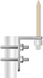
The LRCL is a 5' Foot x 5/8" Copper Clad Lightning Rod that comes threaded, with Nut and Washer Hardware, for mounting onto Tower Top Assembly Plates (i.e. ROHN APL25G, APL45G, APL55G, APL4A, APL4HA), Leg Mounts and Caps (i.e. ROHN VW133, VW132, VY1949A, VY1949-A) as well as extraneous Mounts such as the Harger CUBU581 Air Terminal Base.
Installs on most Tower Series Top/Beacon Plates and attachments made for this purpose.
Many computer users are discovering the benefits of wiring their homes and offices for network connectivity for Printers, computer networks and home entertainment. By installing a patch panel and network ports, connecting computers or accessories to your network becomes simple and quick.
Get a cabling punch down tool, a network cable tester and a network cable patch panel for RJ45 connections with the number of ports you need. Choose a place to mount the panel in the area where the network cables terminate. There is an "A" color code on the connectors and the "B" color code. Use the "B" code, which is the common network standard.
Trim off damaged areas using scissors on the outer jacket or sharp bends from the network cables you will connect to the panel. Use the cable stripper to score the jacket about 1½ inches from the end. Remove the scored jacket and untwist each pair of wires that make up the cable. Gently straighten each wire and fan them out from the cable end. Keep matching colors together; for example, keep orange with orange and white, and blue with blue and white. Lay the fan between the two rows of connectors on the patch panel for the port you wish to use. Match each wire to the corresponding color in the "B" color scheme. Gently pull the wire between the two halves of the connector for each color. Use the punch down tool to push the cable completely in to each connector. Be sure the cutting edge on the tip of the tool is on the outside of the connector so that it trims the excess cable flush. Repeat for each wire. Use the cable tester to ensure good connectivity between the panel and the wall ports where the cables end. Connect the remote terminator to the port in the panel, then connect the cable tester to the wall port at the other end of the cable. Check the tester's lights for a good connectivity reading. Repeat for the remaining ports.