ROHN Camera Towers
ROHN structures can be designed to be utilized for security towers and surveillance applications. Our security towers are supporting cameras at military and government installations around the world. We have both solid and tubular security tower designs and all welded or knock-down designs to meet your security needs.
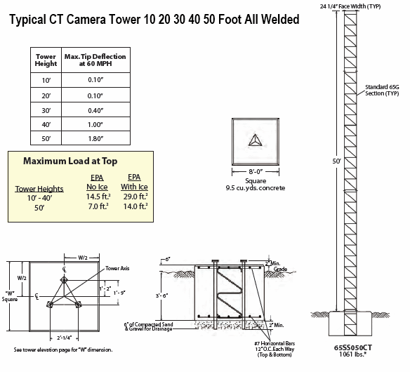
The all welded 65G tower sections can support 14.5 square feet of camera in 90mph, ½" ice conditions. ROHN has standard 65G security camera towers from 10´ up to 50´. ROHN also designs site-specific towers for security applications in all wind and ice conditions. Our rigid designs limit tower top movement to help ensure camera functionality even through severe weather conditions.
STANDARD VG SELF-SUPPORTING CAMERA TOWERS (all-welded)
REV. G:
110 MPH 3-SEC GUST WIND SPEED (NO ICE),
40 MPH 3-SEC GUST WIND SPEED (3/4" ICE),
CLASS II , EXPOSURE C , TOPO CATEGORY 1
SEISMIC COEFFICIENT S <1.0

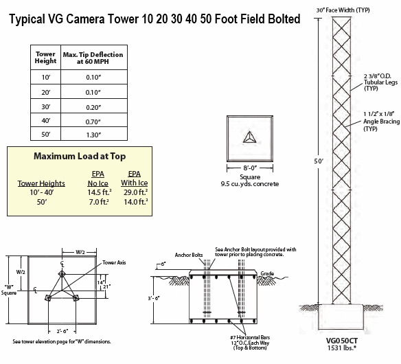
STANDARD VG SELF-SUPPORTING CAMERA TOWERS (field bolted)
REV. G:
110 MPH 3-SEC GUST WIND SPEED (NO ICE),
40 MPH 3-SEC GUST WIND SPEED (3/4" ICE),
CLASS II , EXPOSURE C , TOPO CATEGORY 1
SEISMIC COEFFICIENT S <1.0

DESIGN NOTES:
1. Tower designs are in accordance with ANSI/TIA/222-G.
2. Camera and mount assumed symmetrically placed at tower top.
3. Tower design assumes one 7/8" line on each tower face.
4. Assembly drawings and standard foundation details are provided with the tower.
5. Standard foundation illustrated is for general information only and is based on Rev G presumptive clay soil parameters.
FEATURES:
o Completely hot-dip galvanized after fabrication to provide absolute corrosion protection.
o Pre-engineered loading charts meet varying individual specs and site conditions.
o Typical uses include small dishes, broadband, security and two-way communication.
![]()
ROHN G-Series Self Supporting Towers
![]()
This ROHN G-Series Self Supporting Towers Guide will answer many questions you may have on this Product Line.
GUIDELINES FOR THE PREPARATION OF A GEOTECHNICAL REPORT
I. PURPOSE AND INTENT
a) The intended purpose of these guidelines is to assist the customer and/or owner to retain the services of a Geotechnical Engineer.
b) It is not ROHN´s purpose or intent to supercede the Geotechnical Engineer´s knowledge, judgement and/or experience. It is the Geotechnical Engineer´s responsibility to add or delete from these items, based on local site conditions and other factors.
c) Additional information is provided in ANSI/TIA-222-G Annex G "Geotechnical Investigations".
II. DISCLAIMER
a) ROHN will not accept any liability, either expressed or implied, for the use of, and omissions in, these guidelines.
III. EXPLORATORY BORINGS
a) Borings should be taken at tower legs for self-supporting towers and at the base and anchor points for guyed towers. For small self-supporting towers, two borings may suffice. For large self-supporting towers, one boring should be taken at each tower leg. A "small" self-supporting tower is assumed to have a face width less than 20 feet and a compression load less than 50 kips per leg. For pole structures, one boring may suffice.
b) The minimum boring depth should be 30 feet for pole structures, self-supporting towers and guyed tower bases. For guyed tower anchors, the minimum depth should be 15 feet. The actual depth of boring must be determined by the Geotechnical Engineer based on reactions, soil conditions and the type of foundation recommended.
c) If borings cannot be advanced to the desired depth, rock corings should be taken. Rock Quality Designation (RQD) values and compressive strengths should be determined.
IV. GEOTECHNICAL REPORT
a) The following properties, for each soil layer encountered, should be determined by field or laboratory testing and summarized in the geotechnical report:
1. Soil classification and elevations
2. Standard penetration values
3. Unconfined compression strength
4. Angle of internal friction
5. Cohesion
6. "In-Situ" soil density and moisture content
7. Rock quality designation (RQD) and percent rock sample recovered
8. Other properties unique to site conditions
b) The following items should be discussed in the geotechnical report:
1. Geological description of site
2. Observed and expected ground water conditions
3. Expected frost penetration depth
4. Corrosion potential of soil and corrosion protection recommendations
5. Site access and potential construction difficulties
6. Dewatering or site drainage requirements
7. Backfill material recommendations
8. Settlement considerations
9. Additional information to aid foundation designer
10. Recommended types of foundations
11. Design parameters for uplift, download and lateral load
12. Factor of safety considered when allowable vs. ultimate design parameters are provided
13. Recommended construction techniques and inspections


